When you wire a relay, it’s important to first identify the relay type. You also need to understand its pinout before you wire a relay to ensure each pin is connected correctly. Matching each pin to its function helps prevent mistakes that could lead to electrical issues or damage.
Always follow these safety steps when you wire a relay:
Turn off the power before starting the wiring process.
Use the appropriate wire size and fuses.
Double-check your connections to avoid accidents.
By reviewing relay pin diagrams and datasheets before you wire a relay, you reduce risks at home or work. Proper relay wiring keeps you safe by separating control circuits from high-power loads.
Key Takeaways
-
Always find out what relay you have and look at its pinout before you start wiring. This helps you avoid mistakes and keeps your circuit safe.
-
Follow safety rules like turning off the power. Use the right wire size and fuses. Double-check your connections to stop accidents from happening.
-
Learn what the coil, common, normally open, and normally closed pins do. This helps you wire relays the right way and control circuits safely.
-
Use wiring diagrams and datasheets to help you connect everything. This is important for 3-pin, 4-pin, 5-pin, 6-pin, and 8-pin relays.
-
Test your relay after you finish wiring. If it does not work, check the power, ground, and connections to make sure it works well.
Relay Pin Identification
Knowing how to spot relay pins helps you wire things safely. Every relay has its own way of numbering pins. You need to learn these ways so you do not make mistakes.
Pin Numbering Standards
Relay makers use different rules for pin numbers. The most used ones are NEMA, IEC, and DIN. Each one has its own way to number and name the pins. The table below shows how these rules are different:
| Standard | Terminal Numbering Scheme | Terminal Functions | Coil Terminal Designation |
|---|---|---|---|
| NEMA | Numbers 1 to 14 (varies by relay type) | N.C. terminals: 1-4, N.O. terminals: 5-8, Common terminals: 9-12 | 13 and 14 |
| IEC | Two-digit numbers: first digit = contact set, second digit = terminal function (1=common N.C., 2=N.C., 3=common N.O., 4=N.O.) | Contact sets identified by first digit; terminal function by second digit | A1 and A2 |
| DIN | 85, 86, 30, 87, 87a | 85/86: coil, 30: battery input, 87: N.O., 87a: N.C. | 85 and 86 |
DIN numbers show up a lot in car relays. NEMA and IEC are used in factories and for many other uses. These rules help you know what each pin does, even if you use different relays.
Reading Pin Diagrams
Relay datasheets and labels usually have a pin diagram. This picture shows where each pin is and what it does. Always look at the diagram before you start wiring. Find the symbols for the coil, common, N.O., and N.C. pins. The diagram helps you wire the relay right, no matter which rule it uses.
Tip: If you cannot find a datasheet, try searching the relay’s part number online. Most companies put diagrams on their websites.
Visual Markings
Most relays have marks on the case or near the pins. These marks show pin numbers or what each pin does. For example, you might see 85, 86, 30, 87, and 87a next to the pins. The table below tells you what each DIN pin does:
| DIN Terminal | Circuit Type | Function Description |
|---|---|---|
| 85 | Control (coil) | Coil negative (ground) |
| 86 | Control (coil) | Coil positive (power input) |
| 30 | Load (high current) | Battery positive input |
| 87 | Load (high current) | Normally open output (closes when coil energized) |
| 87a | Load (high current) | Normally closed output (opens when coil energized) |
You should always check these marks before you connect wires. This step helps you stop mistakes and keeps your circuit safe.
Relay Pin Functions
Understanding relay pin functions helps you wire circuits safely and correctly. Each pin on a relay has a special job. You need to know what each pin does before you connect your relay switch.
Coil Pins (85, 86)
You find coil pins on every relay. Pins 85 and 86 form the control side of the relay switch. When you apply power to these pins, the coil inside the relay creates a magnetic field. This field moves the contacts and lets the relay switch turn a circuit on or off.
-
In cars, you usually connect pin 85 to ground and pin 86 to a switched power source.
-
The coil pins let you use a small current to control a much larger load, like headlights or motors.
-
In industrial relays, you use the coil pins in the same way. Sometimes, you see extra parts like diodes or resistors across these pins to protect against voltage spikes.
-
Polarity does not matter unless your relay has a built-in diode.
Common, NO, NC (30, 87, 87a)
The other relay pins control the flow of electricity to your load. Pin 30 is the common pin. It connects to your power source or load. Pin 87 is the normally open (NO) contact. When you energize the relay, pin 30 connects to pin 87. Pin 87a is the normally closed (NC) contact. When the relay is off, pin 30 connects to pin 87a.
Here is a table to help you remember the main pin functions:
| Pin Type | Number of Pins | Function Description |
|---|---|---|
| Coil Pins | 2 | Activate the electromagnetic coil to switch the relay. |
| Common Pin | 1 | Connects to the load; serves as the switching terminal. |
| Normally Open (NO) Pin | 1 | Connects to the common pin when the relay is energized (activated). |
| Normally Closed (NC) Pin | 1 | Connects to the common pin when the relay is not energized (deactivated). |
You see these pins in many relay types, such as single pole single throw and single pole double throw relays.
Multi-Contact Relays
Multi-contact relays, like double pole double throw relays, have more pins and can control more than one circuit at a time. These relays use extra sets of contacts, so you can switch two or more loads with one relay switch.
-
Multi-contact relays often use Form C contacts, which give you both NO and NC outputs.
-
You find these relays in control panels and automation systems.
-
Double pole double throw relays have two sets of common, NO, and NC pins. This setup lets you control two circuits at once.
-
The pinout for these relays includes extra terminals for each pole and throw, making them different from single pole single throw relays.
Multi-contact relays help you build more complex circuits. You can use them to control several devices with one relay switch.
How to Wire a Relay
Wiring a relay correctly helps you control circuits safely and reliably. Each relay type has its own pinout and wiring steps. You must always match the relay coil voltage to your system voltage. Using the wrong voltage can cause overheating, damage, or even fire. Always use a fuse on pin 30 to protect your circuit.
3-Pin Relay
A 3-pin relay is simple and often used for basic on/off control. You usually find these in small devices or simple circuits.
Steps to wire a relay with 3 pins:
-
Identify the pins: one for the coil positive, one for the coil negative, and one for the common contact.
-
Connect the coil positive pin to your control switch or power source.
-
Connect the coil negative pin to ground.
-
Attach the common contact pin to your load or device.
Tip: Always check the relay diagram to confirm which pin is which. Never guess the pinout.
4-Pin Relay
A 4-pin relay is common in automotive and industrial circuits. It gives you simple on/off control for one device.
How to wire a relay with 4 pins:
-
Find pins 85 and 86 for the coil. Connect pin 85 to ground and pin 86 to your control switch or 12v relay power source.
-
Connect pin 30 (common) to your battery or main power source. Always use a fuse on this line for safety.
-
Attach pin 87 (normally open) to your load, such as a light or motor.
-
When you activate the relay switch, pin 30 connects to pin 87, powering your load.
For best results, mount the relay in a dry, safe place. Use wire loom or conduit to protect your wires. Make all connections with proper crimping or soldering. After you wire a relay, test it to make sure it works. Adding a diode across the coil (between pins 85 and 86) protects your electronics from voltage spikes when the relay turns off.
Note: Always connect the power source to the common terminal (pin 30) and the load to the normally open terminal (pin 87). This method keeps your wiring safe and makes future changes easier.
5-Pin Relay
A 5-pin relay gives you more control. It has both a normally open (NO) and a normally closed (NC) contact. This lets you switch between two circuits or control devices in two states.
How to wire a relay with 5 pins:
-
Identify pins 85 and 86 for the coil. Connect as you would for a 4-pin relay.
-
Pin 30 is the common terminal. Connect it to your power source with a fuse.
-
Pin 87 is the normally open contact. Connect your first load here.
-
Pin 87a is the normally closed contact. Connect your second load or use it for a fail-safe circuit.
When the relay is off, pin 30 connects to pin 87a. When you activate the relay, pin 30 switches to pin 87.
Here is a table to show the difference between 4 and 5 pin relays:
| Aspect | 4-Pin Relay (SPST) | 5-Pin Relay (SPDT) |
|---|---|---|
| Coil Terminals | 85 and 86 | 85 and 86 |
| Contact Terminals | 30 (Common), 87 (Normally Open) | 30 (Common), 87 (Normally Open), 87a (Normally Closed) |
| Default State | 30 and 87 disconnected (open circuit) | 30 and 87a connected, 30 and 87 disconnected |
| Energized State | 30 and 87 connected (closed circuit) | 30 and 87 connected, 30 and 87a disconnected |
| Switching Type | Single-pole, single-throw (SPST) | Single-pole, double-throw (SPDT) |
| Functional Feature | Simple on/off switching | Dual-state switching with break-before-make operation |
| Wiring Complexity | Simpler wiring with 4 pins | More complex wiring with 5 pins |
| Preferred Scenarios | Unidirectional switching, space-constrained, cost-sensitive projects | Dual-state control (motor reversal, beam switching), fail-safe systems, smart devices with state feedback |
You should use a 5-pin relay when you need to switch between two circuits or want a fail-safe option. For example, you can use it to reverse a motor or switch between two lights. Always check 5 pin relay schematics before you start wiring a relay.
6-Pin Relay
A 6-pin relay often has extra contacts for more complex control. You might see these in automation or control panels.
Key points when you wire a relay with 6 pins:
-
Two pins connect to the coil. Make sure you match the coil voltage to your control signal.
-
The relay has common terminals for the switch contacts.
-
You get both normally open and sometimes extra contacts for special functions.
Steps:
-
Identify the coil pins and connect them to your control circuit.
-
Find the common, NO, and any extra contacts.
-
Connect your power source and loads as shown in the relay diagram.
-
Double-check all connections before you power up.
Always check if your 6-pin relay has special features or extra contacts. Some relays use the extra pins for indicator lights or feedback signals.
8-Pin Relay
An 8-pin relay is used in advanced circuits, like home automation or industrial control. It can control multiple devices at once.
Best practices for wiring an 8-pin relay:
-
Disconnect all power before you start.
-
Use a voltage tester to make sure no current is present.
-
Wear insulated gloves and safety glasses.
-
Inspect all wires and the relay base for damage or loose connections.
-
Follow the wiring diagram for your specific relay model.
-
Use the right tools for stripping, connecting, and testing wires.
-
Connect the coil terminals (usually pins 1 and 2) to your control voltage. Make sure the voltage matches the relay coil rating, such as a 12v relay.
-
Connect pin 3 (common), pin 4 (normally closed), and pin 5 (normally open) to your loads as needed.
-
Secure all connections and mount the relay to avoid stress on the pins.
-
Test the relay under real load conditions. Listen for a click or use a multimeter to check operation.
-
Perform regular checks for wear, corrosion, or loose wires.
Always use a flyback diode across the coil to prevent voltage spikes. Never exceed the relay's contact current rating. When you wire a relay with an 8-pin base, follow the diagram closely to avoid mistakes.
Common uses for an 8-pin relay:
-
Home automation
-
Industrial control circuits
-
Automotive electronics
-
Power supply control
When you wire a relay, always match the coil voltage to your control signal. Using a 12v relay in a 24V system can cause overheating, relay failure, or even fire. Always use a fuse on pin 30 to protect your circuit and equipment.
Wiring Diagrams and Safety
Sample Wiring Diagrams
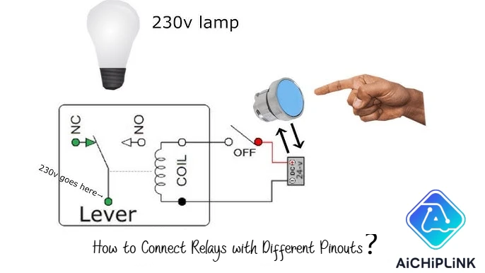
You can use sample wiring diagrams to understand how to connect relays with different pinouts. These diagrams show you where each wire goes and help you avoid mistakes. For example, a common 5-pin automotive relay uses pins 85 and 86 for the coil. Pin 85 usually goes to ground, and pin 86 connects to a switchable power source. Pin 30 connects to the power supply, pin 87a is the normally closed contact, and pin 87 is the normally open contact. When you energize the coil, pin 30 switches from 87a to 87. This setup lets you control either a normally open or normally closed circuit.
Sample wiring diagrams also show how to wire 4-pin relays. In these, pins 85 and 86 control the coil, and pins 30 and 87 switch the load. You can use these diagrams for tasks like adding driving lights or warning buzzers. Relay wiring diagrams help you see the differences between relay types and make sure you connect everything correctly.
Safety Tips
You must always follow safety rules when working with relays.
-
Turn off all power before you start wiring or replacing a relay.
-
Never remove the relay case or cut the terminals.
-
Do not use bent or damaged terminals.
-
Use the right soldering tools and keep terminals clean.
-
Use the correct sockets and tighten all screws to the recommended torque.
Wiring diagrams help you avoid common mistakes. They show you the right wire size and help you trace each connection. Always double-check relay pin functions using the relay schematics and diagrams before making final connections.
Tip: Mark each step on your wiring diagrams as you finish it. This habit helps you avoid missing any connections.
Troubleshooting
If your relay does not work, you can follow a few simple steps.
-
Break the circuit into sections, such as the load, relay, and wiring.
-
Start testing from the load and move back toward the power source.
-
Swap relays or loads with known good parts to find the problem.
-
Use a test light or multimeter to check for power and ground at each point.
-
Inspect all connections for corrosion or loose wires.
You can also listen for a click when you power the relay. If you do not hear it, check the coil voltage and resistance. Relay wiring diagrams and regular inspection help you find and fix problems quickly.
You should first figure out what relay type you have. Next, learn the pinout and what each pin does. Do not connect wires until you know this. Follow each wiring step one at a time. Use diagrams to help you see where each wire goes. Always check your work so you do not make mistakes. The table below shows important safety tips for relay wiring:
| Key Point | Description |
|---|---|
| Power Connections | Safety relay needs 24VDC on A1 and A2. |
| Dual Redundancy | Use dual channels for safety and reliability. |
| Testing Procedure | Test relay in a closed loop to ensure proper function. |
If you need more help, look for expert guides and FAQs online. You can also find troubleshooting tips for relay wiring and safety. Trusted sites like Omron’s relay support page are good places to check. Always use these resources to keep your projects safe and working well.
FAQ
How do you find the correct pinout for an unknown relay?
You can check the relay’s case for numbers or symbols. If you see nothing, search the part number online. Most manufacturers provide datasheets with pin diagrams. Always match the diagram to your relay before you start wiring.
Can you use a 5-pin relay instead of a 4-pin relay?
Yes, you can use a 5-pin relay in place of a 4-pin relay. Just leave pin 87a (normally closed) unconnected. The relay will work like a 4-pin type.
What happens if you connect the coil pins backward?
Most relays work fine if you swap coil pins. If your relay has a built-in diode, you must connect the positive and negative correctly. Otherwise, the relay will not work, and you might damage the diode.
Why should you use a fuse with relays?
A fuse protects your circuit from short circuits and overloads. Always place a fuse on the power line to pin 30. This step keeps your relay and connected devices safe.

Written by Jack Elliott from AIChipLink.
AIChipLink, one of the fastest-growing global independent electronic components distributors in the world, offers millions of products from thousands of manufacturers, and many of our in-stock parts is available to ship same day.
We mainly source and distribute integrated circuit (IC) products of brands such as Broadcom, Microchip, Texas Instruments, Infineon, NXP, Analog Devices, Qualcomm, Intel, etc., which are widely used in communication & network, telecom, industrial control, new energy and automotive electronics.
Empowered by AI, Linked to the Future. Get started on AIChipLink.com and submit your RFQ online today!


